MPPT vs. PWM Solar Charge Controllers: Efficiency, Sizing, and Wiring Guide
Compare MPPT and PWM solar charge controllers. Learn how MPPT boosts efficiency by up to 30 percent, how each technology works, sizing rules, and wiring steps.
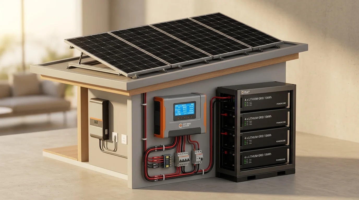
A solar charge controller is the central manager of an off-grid solar energy system. It sits between your solar panels and your battery bank. Its primary job is to regulate the incoming voltage and current, protecting your batteries from overcharging, overheating, and dangerous reverse currents at night.
When building an off-grid cabin, RV power system, boat setup, or emergency home backup, you will choose between two primary technologies: Pulse Width Modulation (PWM) and Maximum Power Point Tracking (MPPT).
While PWM controllers are simple and low in cost, MPPT controllers use advanced electronics to deliver up to 30 percent more usable energy to your battery bank from the exact same solar panels.
Here is a complete breakdown of how MPPT and PWM controllers work, real-world efficiency comparisons, sizing calculations, and step-by-step wiring rules.
Comparing MPPT and PWM Controllers
MPPT Charge Controller
Converts excess panel voltage into extra charging current using a smart DC-to-DC converter. Delivers 20 to 30 percent more power in cold or overcast weather.
PWM Charge Controller
Acts as an electronic on-off switch that pulls panel voltage down to match the battery. Simple and reliable, but wastes excess solar voltage as heat.
Integrated Inverter-Charger
Combines an internal MPPT controller, AC battery charger, and pure sine wave inverter in a single enclosure. Simplifies wiring for whole-house systems.
How Pulse Width Modulation (PWM) Works
A PWM charge controller operates like a high-speed electronic switch. It connects your solar panels directly to your battery bank.
When your battery is low, the switch stays closed, allowing current to flow into the battery. As the battery fills up and nears full charge, the controller rapidly pulses the connection on and off hundreds of times per second. This pulsing tapers down the current to prevent overcharging while holding the battery at its target float voltage.
The Voltage Mismatch Problem
The major drawback of PWM is voltage clipping. A standard 12V solar panel typically produces 18 to 21 volts at its maximum power point (Vmp). However, a discharged 12V battery operates between 11.5 and 12.8 volts.
Because a PWM controller creates a direct electrical link between the panel and the battery, it pulls the panel voltage down to match the battery voltage.
For example, consider a 100-watt solar panel rated for 18 volts and 5.55 amps:
- Panel rated power: 18V x 5.55A = 100 Watts
- When connected through PWM to a 12.5V battery: 12.5V x 5.55A = 69.38 Watts
- Lost power: Over 30 watts of clean solar potential is lost because the panel is forced to operate far below its ideal voltage.
How Maximum Power Point Tracking (MPPT) Works
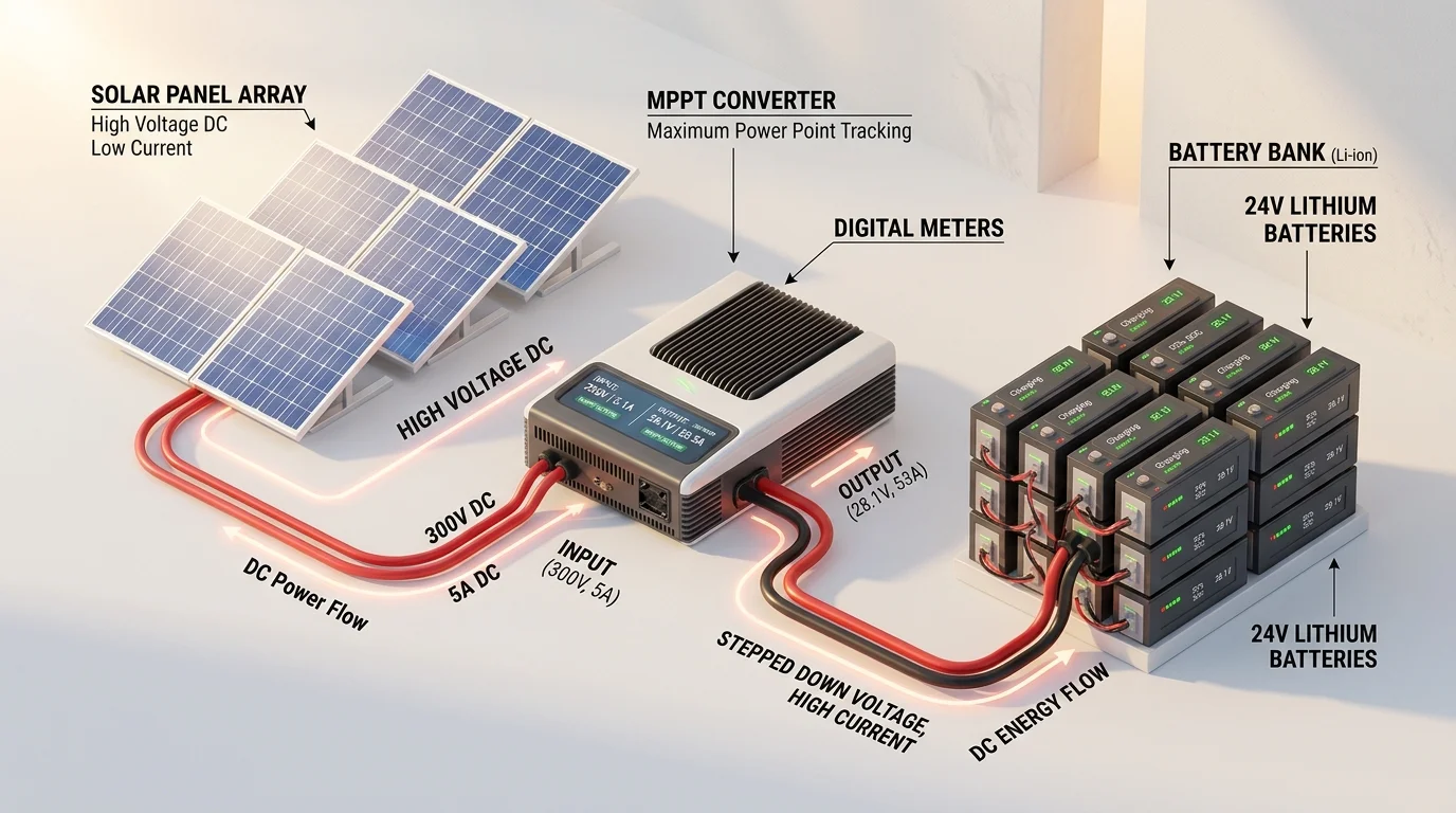
An MPPT charge controller solves the voltage mismatch problem by acting as a smart DC-to-DC power converter.
Instead of clamping the solar panel to the battery voltage, the MPPT controller allows the solar panels to operate at their optimal maximum power voltage (Vmp). An internal computer scans the solar array output hundreds of times per second to track changes in sunlight and temperature.
Once the controller captures the high-voltage DC power from the panels, it steps down the voltage to match the battery bank while simultaneously boosting the charging current.
The Power Conversion Formula
Electrical power follows a simple rule: Watts = Volts x Amps.
If we take the same 100-watt panel (18V at 5.55A) and connect it to a 12.5V battery through an MPPT controller with 97 percent efficiency:
- Solar array input: 18V x 5.55A = 100 Watts
- MPPT conversion at 97 percent efficiency: 97 Watts delivered
- Charging current to battery: 97 Watts / 12.5V = 7.76 Amps
While the PWM controller only delivered 5.55 amps (69.4 watts), the MPPT controller delivers 7.76 amps (97 watts). That is a 39.8 percent increase in charging current delivered to your battery bank from the exact same solar panel.
Temperature Impact: Why MPPT Excels in Cold Weather
Solar panels are semiconductors, meaning their electrical voltage changes based on ambient temperature.
- In cold weather: Solar cell voltage increases significantly. On a clear winter day at 30 degrees Fahrenheit (-1 degree Celsius), an 18V panel can easily produce 21 to 22 volts. A PWM controller clips all of this extra voltage away. An MPPT controller converts every additional volt into extra charging amps, creating a 30 to 40 percent performance advantage.
- In hot weather: High temperatures cause solar panel voltage to decrease. On a 100-degree Fahrenheit (38 degrees Celsius) summer afternoon, panel voltage may drop to 15 volts. Because the panel voltage is now much closer to the battery charging voltage, the MPPT advantage narrows to around 10 to 15 percent.
Sizing a Solar Charge Controller
To choose the correct charge controller size, you need to calculate the maximum continuous charging current (in amps) that will flow from the controller into your battery bank.
Step 1: Calculate Controller Amperage
Use this formula:
- Base Current = Total Solar Wattage / Battery Bank Nominal Voltage
- Controller Size = Base Current x 1.25 (Safety Factor)
The 1.25 multiplier is a standard safety buffer recommended by electrical codes to account for bright cold-weather reflections and edge-of-cloud light spikes.
- Example: A 600-watt solar array on a 12V battery bank:
- Base current: 600W / 12V = 50 Amps
- With safety buffer: 50A x 1.25 = 62.5 Amps
- Recommended controller: A 60A or 70A MPPT charge controller.
Step 2: Check Maximum PV Input Voltage (Voc)
Every MPPT controller has a maximum input voltage rating (such as 100V, 150V, or 250V).
When wiring solar panels in series, their open-circuit voltages (Voc) add together. You must ensure that the total combined Voc of your panel string, adjusted for cold weather, never exceeds the maximum input voltage rating of the controller.
Step-by-Step Charge Controller Wiring Sequence
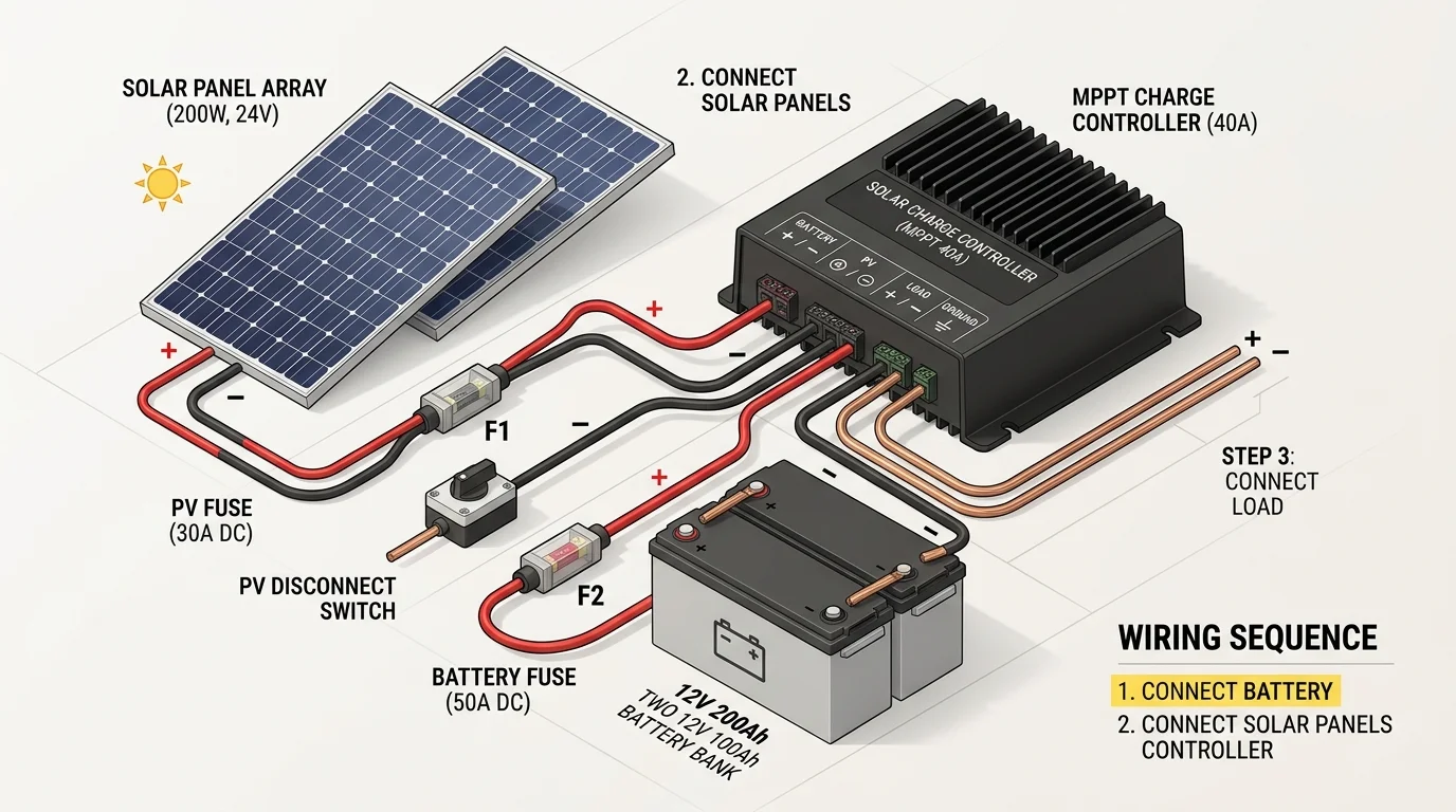
Connecting a solar power system in the wrong order can damage the charge controller microprocessor. Always follow this strict sequence when installing or maintaining your equipment:
Connect the Battery Bank First
Always connect the battery cables to the charge controller before connecting solar panels. The controller needs battery voltage to power its display and configure its internal charging logic.
Install Inline Battery Fuse
Place an appropriately rated DC fuse or circuit breaker on the positive battery cable as close to the battery terminal as possible to protect against short circuits.
Connect Solar Panels via Disconnect Switch
Connect the positive and negative solar array cables. Using an inline DC isolator switch lets you safely turn off solar panel power during maintenance.
Connect Optional DC Loads
If your controller includes dedicated DC load terminals, connect low-power devices like 12V LED lights or fans. Never connect high-power AC inverters to the controller load terminals.
When to Choose PWM vs. MPPT
Choose a PWM Controller If:
- Your total solar array is small (under 150 to 200 watts).
- You are using a single 12V panel to charge a 12V battery.
- You have a strict entry-level budget (PWM units cost $15 to $35 vs. $60 to $150 for MPPT).
- You operate primarily in hot summer conditions where voltage gains are modest.
Choose an MPPT Controller If:
- Your solar array is 200 watts or larger.
- You want to use high-voltage residential solar panels (30V to 50V) on a 12V or 24V battery bank.
- You live in an area with cold winters, overcast skies, or changing light conditions.
- Your solar panels are mounted far from the battery bank (higher voltage strings reduce cable thickness and line loss).
- You plan to expand your solar system in the future.
Frequently Asked Questions
Yes, but only with an MPPT charge controller. An MPPT controller can take high input voltages (up to 100V or 250V depending on the model) and step the voltage down safely to charge a 12V battery bank with maximum efficiency. A PWM controller cannot do this effectively and would waste more than half of the panel capacity.
Connecting solar panels first can destroy the charge controller. Without an active battery connected, the controller cannot establish its reference voltage or regulate the high incoming solar power. This can burn out the internal circuit board. Always connect the battery first, and disconnect the panels first when taking the system apart.
In real-world conditions, an MPPT controller delivers 20 to 30 percent more daily watt-hours to your battery bank than a PWM controller from identical solar panels. In cold winter weather or during cloudy periods, the gain can reach 35 to 40 percent.
No. The DC load terminals on a charge controller are only designed for small, steady electronics like 12V lights, ventilation fans, or USB outlets. Power inverters draw massive surge currents that will trip or damage the controller load circuit. Always connect inverters directly to the main battery bank terminals through a dedicated fuse.
Yes. Most modern MPPT controllers include dedicated preset charging profiles for Lithium Iron Phosphate (LiFePO4) batteries as well as lead-acid, AGM, and Gel batteries. Many models also allow custom voltage programming for bulk, absorption, and float stages.