Solar Panel Grounding and Bonding: NEC Rules, Sizing, and Safety Guide
Understand solar panel grounding and bonding under NEC Article 690, equipment grounding conductor sizing, WEEB clips, and electrical fault protection.
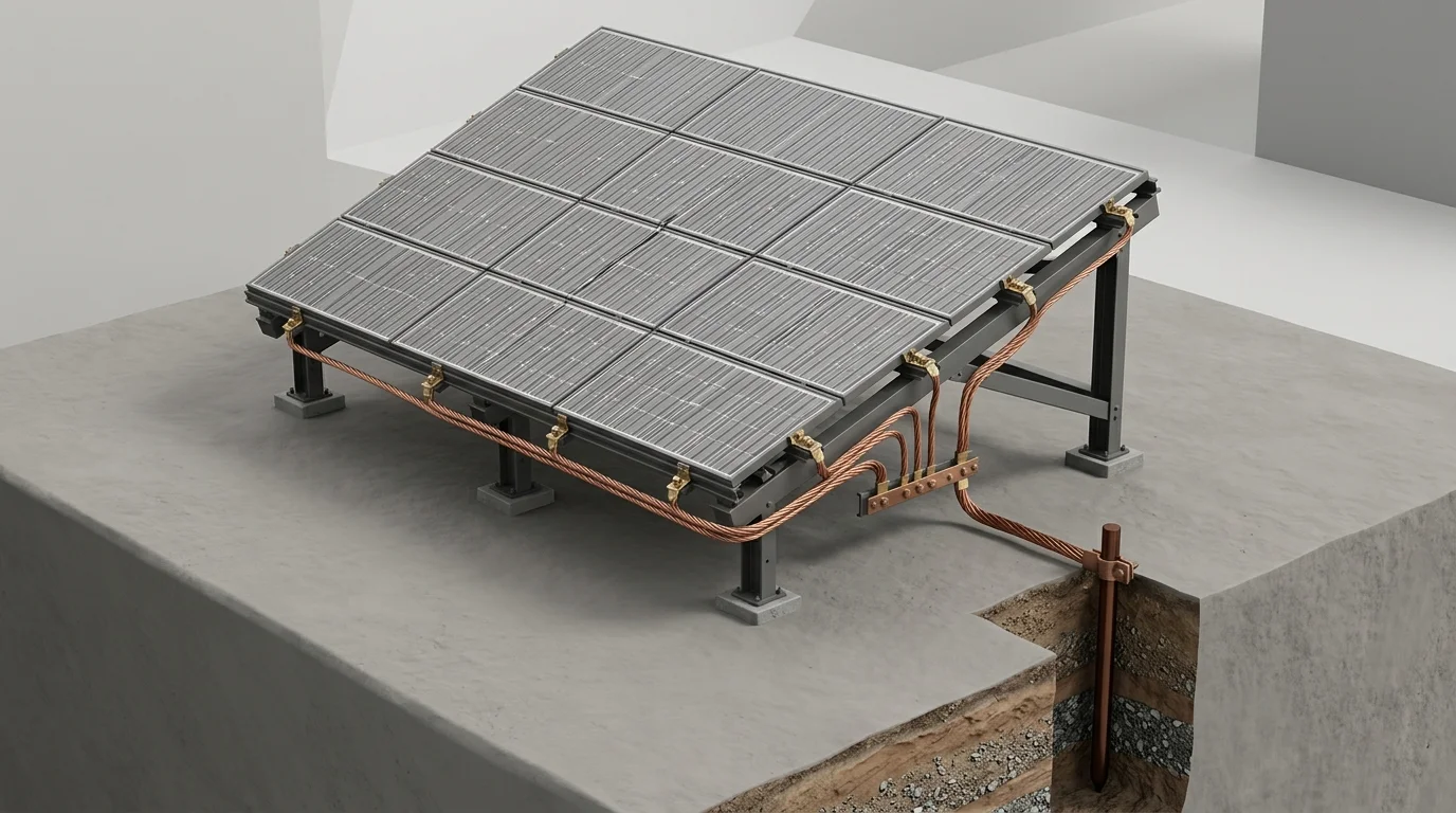
Solar panels sit outdoors on rooftops and open fields for decades. During that time, they endure relentless summer heat, freezing winter moisture, high winds, and lightning storms. Because solar arrays generate hundreds of volts of direct current (DC) electricity, keeping people and property safe from electric shocks and fires is essential.
Proper electrical grounding and bonding form the safety foundation of every solar power system. When done right, this protective network shields homeowners from dangerous touch voltages, redirects dangerous fault currents safely back to circuit breakers, and channels lightning surges directly into the earth.
Yet grounding and bonding remain two of the most misunderstood topics in solar energy installation. Many people use the words interchangeably, but in electrical engineering, they perform two completely separate jobs.
Solar Grounding vs. Bonding: What Is the Difference?
To understand how solar safety systems work, it helps to separate the two core concepts defined in the National Electrical Code (NEC Article 100 and Article 690):
- Bonding (Joining Metal Parts Together): Bonding connects all exposed, non-current-carrying metal parts so they form a continuous, low-resistance electrical path. This includes the aluminum panel frames, steel racking rails, metal conduits, and inverter enclosures. If a damaged wire touches an aluminum rail, bonding ensures that the electrical current can travel smoothly without building up dangerous high voltages on the metal surfaces.
- Grounding (Connecting to the Earth): Grounding connects the bonded electrical system to the physical earth through grounding rods, rebar in concrete foundations, or buried plates. This connection stabilizes electrical voltages against lightning strikes, static electricity, and utility line surges.
Key Rule: Bonding protects human beings from electrical shock during a wiring failure. Grounding protects buildings and equipment from high-voltage surges like lightning and static electricity.
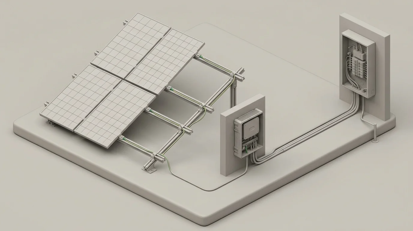
A common myth is that electrical fault currents want to flow into the dirt. In reality, electricity seeks a closed loop back to its power source (the electrical service panel or inverter). Earth soil has high electrical resistance and cannot trip a circuit breaker on its own. Bonding provides the clear highway that allows breakers and safety fuses to open quickly.
The Three Layers of Solar Grounding Protection
Modern solar installations rely on three interlocking grounding systems specified across NEC Article 690:
1. Equipment Grounding Conductor (EGC)
Under NEC Section 690.43, every exposed metal module frame, rail, combiner box, and metal conduit must connect to an Equipment Grounding Conductor (EGC). If an energized conductor frays or pinches against a sharp metal edge, the fault current races through the EGC back to the ground-fault detector or overcurrent protective device (OCPD), safely tripping the circuit in milliseconds.
2. Grounding Electrode Conductor (GEC)
The Grounding Electrode Conductor (GEC) is the heavy copper wire that connects the main electrical service panel or solar disconnect switch to the physical grounding electrode (usually an 8-foot copper rod driven into the earth). Under NEC Section 690.47, rooftop residential solar systems tie their GEC directly into the home existing electrical grounding electrode system, maintaining an equal electrical potential across the entire building.
3. System Grounding (Inverter Dependent)
System grounding refers to whether one of the actual current-carrying electrical conductors (positive or negative DC wire) connects to earth:
- Legacy Transformer Inverters: These older, heavy inverters required solid grounding of the negative DC wire under NEC Section 690.41(A).
- Modern Transformerless Inverters: Modern residential inverters (such as string inverters and microinverters) operate as floating, ungrounded DC systems under NEC Section 690.41(B). They rely on sensitive internal Ground Fault Detection and Interruption (GFDI) electronics. Solidly grounding a DC wire on a modern transformerless inverter will cause severe system errors and equipment damage.
Hardware Essentials: WEEB Washers, Bonding Jumpers, and Lugs
Because aluminum naturally develops a thin, insulating layer of oxidation when exposed to air, standard metal bolts alone cannot guarantee a reliable electrical connection over a 25-year lifespan. Solar installers use specialized, code-approved bonding hardware:
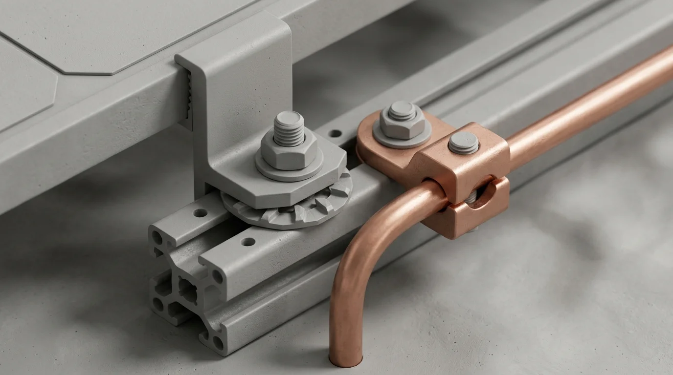
- WEEB Washers (Washer, Electrical Equipment Bond): These small, stainless-steel washers feature sharp microscopic teeth. When installers tighten module mid-clamps to the manufacturer torque specification (typically 10 to 15 foot-pounds), the teeth bite through the anodized aluminum coating of the panel frame and racking rail. This creates a gas-tight, corrosion-resistant electrical bond tested under UL 2703 standards.
- Bonding Jumpers: When racking rails end or cross building expansion joints, flexible copper or tin-plated bonding jumpers bridge the gap to maintain uninterrupted continuity across the array.
- Lay-In Grounding Lugs: Tin-plated copper lugs bolt directly to the end of each racking rail row. Installers run a solid bare copper wire through the lay-in slot, clamping it down securely without cutting the conductor.
How to Size Solar Grounding Wires (NEC Table 250.122)
Sizing the Equipment Grounding Conductor correctly is vital to pass building inspections and prevent wire overheating during a fault. Sizing depends on the rating of the fuse or circuit breaker protecting the circuit, following NEC Section 690.45 and NEC Table 250.122.
| Circuit Overcurrent Protection (OCPD) | Minimum Copper EGC Wire Size | Minimum Aluminum EGC Wire Size | Typical Solar Application |
|---|---|---|---|
| 15 Amps | 14 AWG | 12 AWG | Single microinverter branch or small DC string |
| 20 Amps | 12 AWG | 10 AWG | Standard residential branch circuit |
| 30 Amps | 10 AWG | 8 AWG | High-power PV output circuit or AC trunk |
| 40 Amps | 10 AWG | 8 AWG | Multi-branch residential solar combiner |
| 60 Amps | 10 AWG | 8 AWG | Large residential or light commercial inverter |
| 100 Amps | 8 AWG | 6 AWG | Commercial solar subpanel feeder |
| 200 Amps | 6 AWG | 4 AWG | Main commercial solar distribution panel |
Assumed OCPD Sizing for Single DC Strings
Many single-string solar arrays do not have an inline fuse because a single string cannot produce enough backfeed current to overload its own wiring. In these cases, NEC Section 690.45 instructs installers to calculate an “assumed” OCPD rating:
- Identify the module short-circuit current (Isc), for example, 10.2 Amps.
- Multiply by 1.25 to find maximum circuit current: 10.2 A × 1.25 = 12.75 Amps.
- Multiply by 1.25 again for continuous duty: 12.75 A × 1.25 = 15.94 Amps.
- Round up to the next standard fuse size: 20 Amps.
- Refer to NEC Table 250.122: A 20-Amp assumed OCPD requires a minimum 12 AWG copper grounding wire.
Installer Best Practice: While 10 AWG or 12 AWG copper meets electrical code minimums, most professional installers run a 6 AWG bare solid copper wire across rooftop racking. Under NEC Section 250.120(C), 6 AWG wire is robust enough to run exposed along rails without requiring rigid conduit, protecting it against physical damage from snow, wind, and maintenance crews.
4-Step Checklist for Safe Solar Grounding Installation
Mount UL 2703 Listed Racking
Assemble aluminum mounting rails and torque module mid-clamps with integrated bonding pins or WEEB clips. Ensure all metal teeth pierce panel anodization.
Install Bonding Jumpers Across Rails
Bridge every rail splice and row transition with certified bonding jumpers to guarantee end-to-end electrical continuity under 0.1 ohm resistance.
Secure Lay-In Lugs and 6 AWG Copper
Mount tin-plated copper lugs to the rail ends. Thread a continuous 6 AWG bare copper conductor through each lug and torque the set screws to spec.
Tie into the Main Grounding Electrode
Route the grounding wire through conduit down the building exterior and bond directly to the home main grounding busbar or ground rod system.
Cost Analysis: Solar Grounding Hardware and Protection
Grounding and bonding equipment accounts for a small fraction of total solar installation costs, but it delivers the highest safety return on investment of any system component.
Bare Bones Minimal Grounding
Uses minimum 10 AWG wire inside conduit with basic bonding clips. Passes basic local inspection but provides less mechanical defense against extreme weather.
Premium Heavy-Duty Protection
Features solid 6 AWG bare copper, dual lay-in lugs, heavy stainless jumpers, and integrated Type 2 surge protective devices (SPD) on both AC and DC disconnects.
Ungrounded Array Hazard
Skipping proper bonding allows unnoticed ground faults, electric shock hazards on roof gutters, fried inverter logic boards, and denied insurance claims.
On a typical 8-kilowatt to 10-kilowatt residential array, comprehensive grounding hardware adds approximately $0.02 to $0.04 per watt. When balanced against the potential cost of replacing a damaged inverter or repairing fire damage, high-quality grounding hardware is indispensable.
Frequently Asked Questions About Solar Grounding
Rooftop solar arrays generally do not need a separate ground rod. In fact, driving a separate, isolated ground rod without bonding it to the home main electrical service can create dangerous electrical potential differences during a lightning strike. Rooftop systems should bond directly back to the existing home grounding electrode system. Ground-mounted systems located far from the main house, however, usually require an auxiliary ground rod bonded back to the main service panel.
Solar panel manufacturers apply an anodized oxide coating to aluminum frames to protect them from weather and corrosion. This coating acts as an electrical insulator. If an installer uses standard bolts without teeth or piercing pins, current cannot pass between the panel and the mounting rail. UL 2703 listed bonding clips and WEEB washers solve this problem by biting directly into the raw aluminum beneath the coating.
When a live wire touches a metal rail or frame, the Equipment Grounding Conductor carries the fault current back to the inverter. Modern inverters continuously monitor insulation resistance. When they detect a ground fault, their internal Ground Fault Detection and Interruption (GFDI) system immediately isolates the array and stops power conversion, showing an error code on the inverter screen or mobile monitoring app.
Direct lightning strikes carry immense energy that can damage any electrical structure. However, proper grounding and bonding provide a safe, low-resistance direct path into the earth for electrostatic charge buildup and nearby indirect strikes. Adding a dedicated Type 1 or Type 2 Surge Protective Device (SPD) on the solar combiner or inverter provides vital secondary protection against destructive voltage spikes.